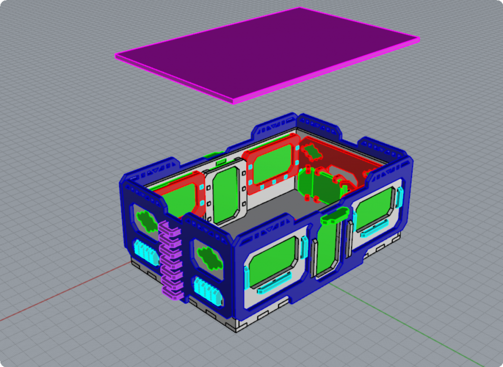
IMPORTANT: It is *HIGHLY* recommended that you assemble the kit “dry” first, without any glue and only once you’ve assembled the entire kit and know everything goes together you can then take the pieces which require glueing apart and glue them together using wood glue.
Assembling the Front / Back Walls
STEP 1 – The Middle Door Assembly
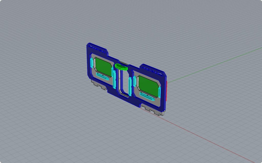
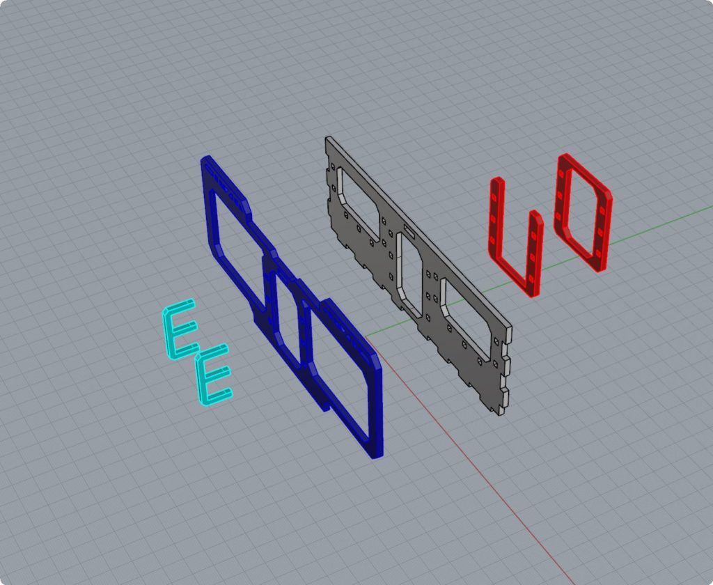
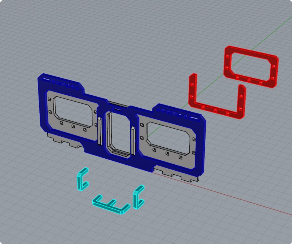
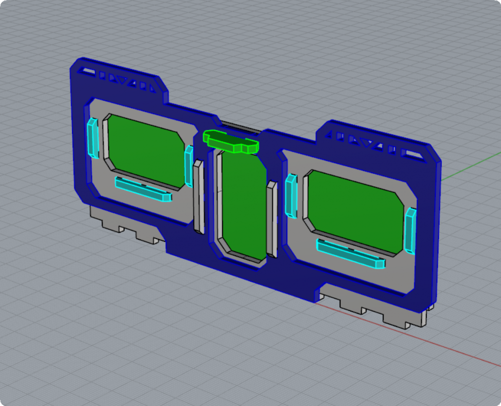
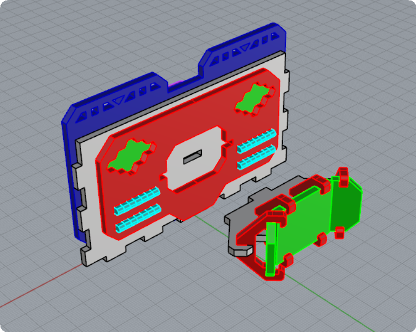
Start by assembling the middle door assembly. Locate the two “E” clips which are longer in your kit. Please note that there are other “E” clips in the kit where the three prongs of the “E” are shorter, which will be used for the next steps for assembling the windows. DO NOT use these shorter clips. Use the longer ones instead.
Carefully insert the prongs of the two “E” clips into the three holes in the middle section of the front piece of the building (shown in dark blue above).
Then, carefully align the prongs so that they go through the three holes of the middle section of the main piece of the building (shown in grey above).
Finally, carefully align the “U” shaped spacer (shown in red above) onto the three prongs of the “E” clip, followed by the “O” shaped door hatch (shown in red above).
The prongs of the “E” clip should fit snugly into the holes but should not be forced in. Push the “E” clip into the holes evenly distributing the pressure across the three prongs so as not to break them.
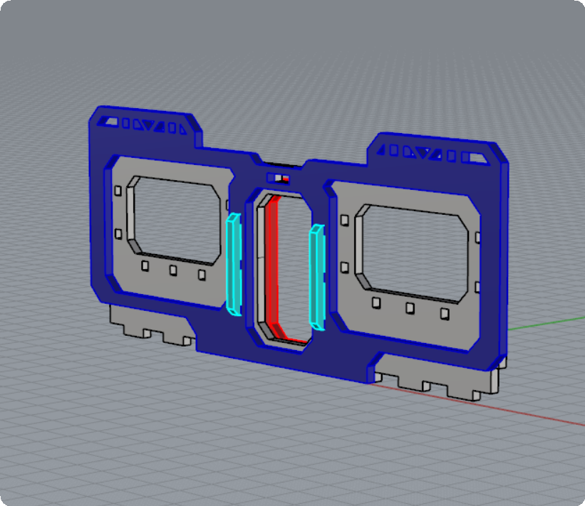
Once assembled the front door assembly should look like this:
Step 2 – Windows Assembly
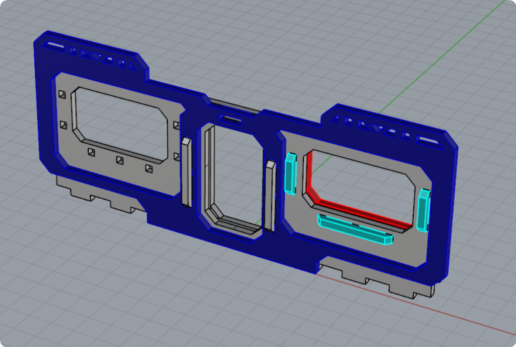
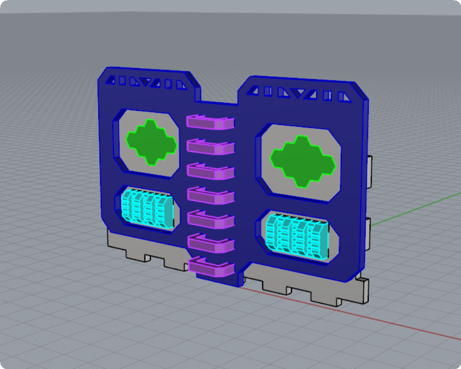
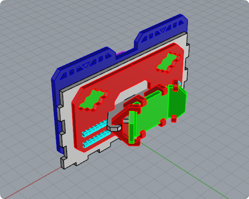
To assemble the windows, start by locating one of the shorter sized “E” clips (shown in light colored blue above). Remember that there are several “E” shaped clips in your kit, some have shorter and some have longer prongs. The longer pronged ones are for the middle doors. The shorter pronged ones are for the windows.
Also, locate two “C” shaped clips that will fit into the holes located on each side of the window (shown in light colored blue above). Please note that the kit also comes with a number of “C” shaped clips which are used for the ladders on the side of the building. In order to be able to tell the window “C” clips apart from the ladder “C” clips, the window “C” clips are made slightly taller. If you try to fit a ladder “C” clip into the the holes intended for the windows “C” clip, you’ll notice that the ladder ones don’t fit. IMPORTANT: DO NOT try to force these “C” clips into the window holes. If it’s not fitting properly, most likely you are trying to use a ladder “C” clip instead of a window “C” clip.
Once you’ve located the proper “E” and “C” clips for the window, also locate the window “U” shaped spacer and “O” shaped window frame (shown in red above).
Carefully insert the “E” and two “C” clips into the corresponding holes located around the window with the prongs facing into the building (as shown above). Apply even pressure when inserting the clips so as not to break them. The clips should be snug but you should not have to force them into place.
Once the clips are inserted into the main wall of the building, proceed to carefully slide on the “U” shaped spacer and then the “O” shaped window frame onto the prongs of the clips.
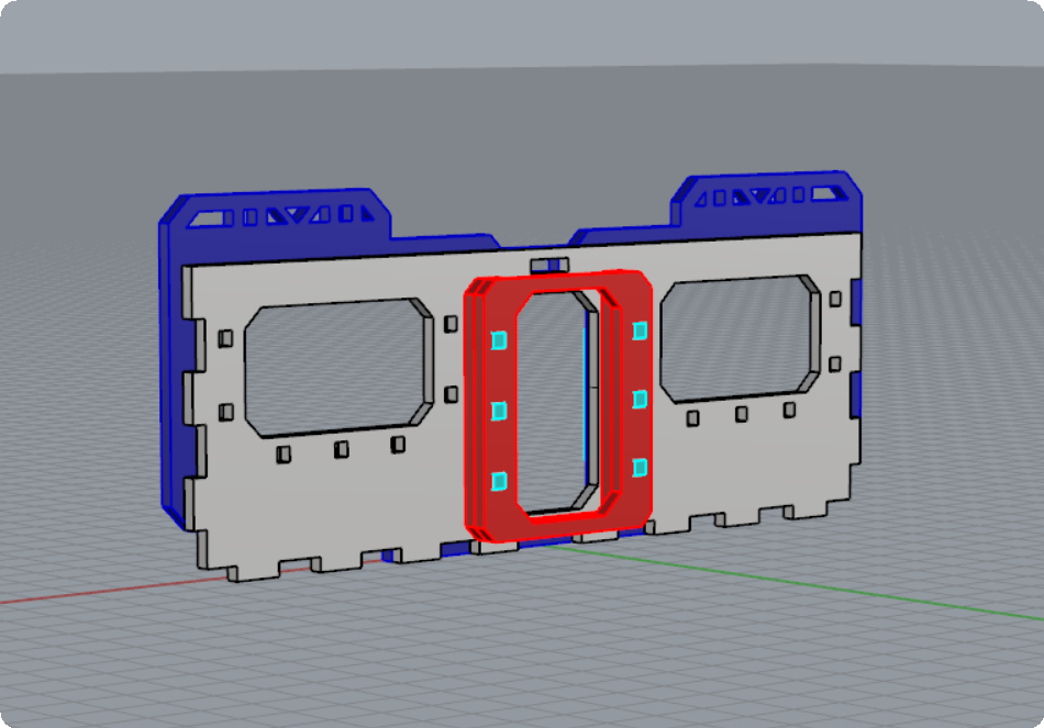
Once assembled the window frame should look like this:
Repeat the process for the other window.
Step 3 – Removable Doors and Windows
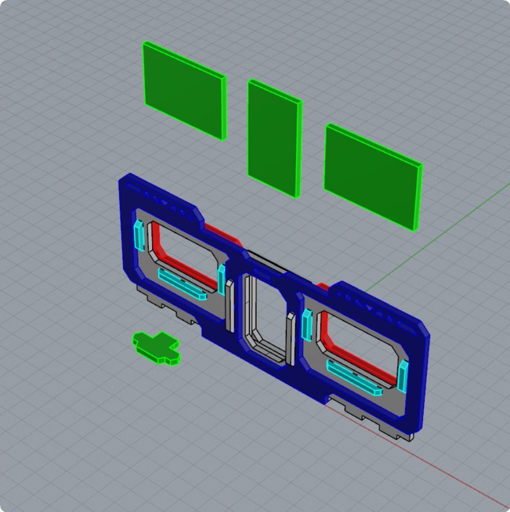
Included in your kit you will find an overhead door light, two windows and a door for each of the front/back walls supplied in two variations. One variation of these pieces is made from the same MDF wood as the rest of the kit. You can paint these pieces any color of your choosing – such as for example painting them a metalic color to signify armored doors/windows etc.
The other variation included in your kit is the same pieces are provided in acrylic plastic. These pieces are extra / optional pieces which you can swap out for the MDF versions.
IMPORTANT: You do NOT need to glue either the MDF or the acrylic versions of the windows / doors into place. The design of the terrain is such so that the doors and windows are REMOVABLE / SWAPPABLE at any time, allowing you to use the terrain in various ways. For example, you could say that when you have the MDF windows/doors inserted, they represent a closed window/door, and when you have the acrylic pieces inserted for the doors/windows, it may represent a “force field” type door/window. Finally you can remove the doors and/or window pieces to represent an open door/window allowing for line of sight into the buildings.
Similarly the acrylic can represent glass windows/doors which, if fired upon can be shattered and to represent that you just remove the acrylic. It’s entirely up to you how you use these elements of the terrain.
Once fully assembled the Front / Back walls should look like this:
REPEAT THE SAME PROCESS FOR THE OTHER FRONT/BACK WALL OF THE BUILDING.
Assembling the Side Walls
Step 1 – Ladder Assembly
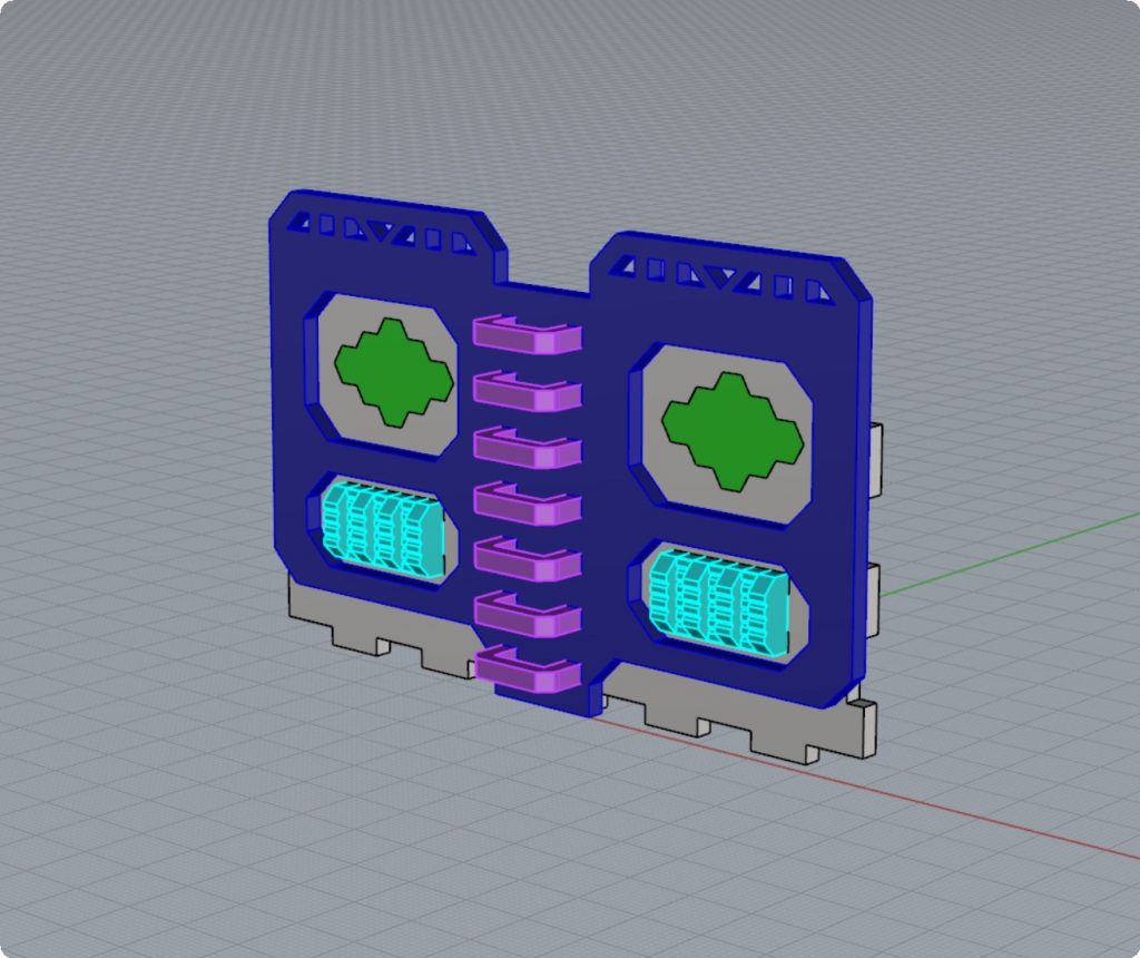
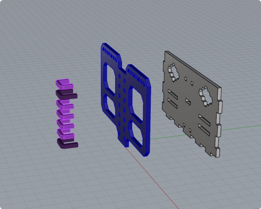
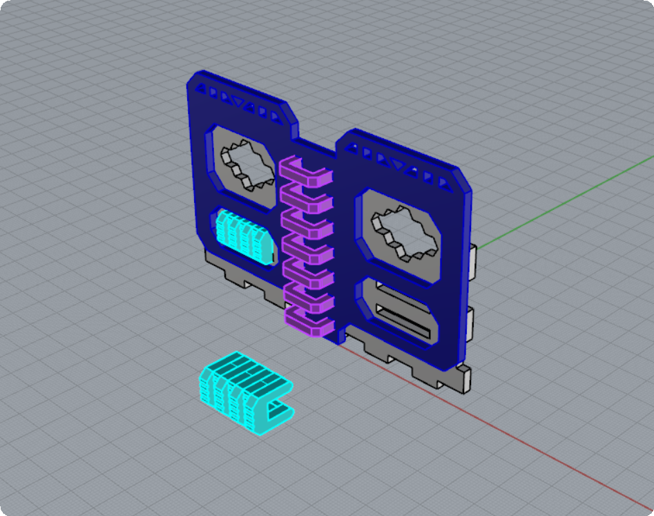
To assemble the ladder, locate the seven “C” clips which make up the rungs of the ladder. Please note that two of the “C” clips will have slightly longer prongs (shown in darker purple above) and five of the “C” clips will have shorter prongs (shown in purple above). Please also note that your kit comes with other “C” clips which are slightly wider, which are meant for the Front/Back wall windows. If you assembled the Front / Back walls first you would have used up these clips, but if you are assembling these side walls first be careful not to mix these up.
Once you’ve located the proper “C” clips in your kit, carefully insert the two longer “C” clips (dark purple above) in the second from the top and the very bottom ladder holes in the outer wall (dark blue above). These two “C” clips will fit into the holes and stick out about 3mm past the other side of the outer wall (blue above).
Next, carefully align the inner wall (grey above), so that the prongs of the two “C” clips align with the two sets of ladder holes in of the inner wall (grey above).
The reason why these two clips were designed to be longer is so that they act as a sort of “key” that joins the two parts of the wall together so that they are perfectly aligned and will make it much easier for you to glue the pieces together later on.
Once you’ve inserted the two longer “C” clips, now proceed to insert the remaining five “C” clips which make up all the rungs of the ladder.
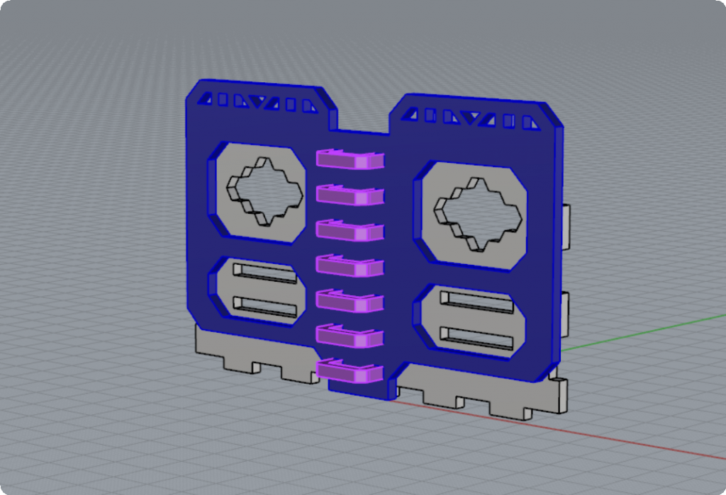
Once assembled, your ladder should look like this:
Step 2 – Power Generators
Your kit comes with two “Power Generator” units located on the Left/Right side of each of the side walls. Of course these parts of the terrain can be made to represent anything you want, such as air-conditioning units or refrigeration units or computer banks or anything else you like. In either case here is how they fit together.
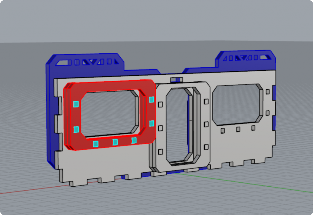
Locate seven “C” shaped clips which look like the ones above in light blue.
Each unit is made up of seven “ribs” which come in two sizes. Four of the “ribs” are slightly wider and stick out a bit more with a more rounded side to them, while three of the “ribs” are slightly narrower with a flatter edge on one side. The ribs fit into the two rectangular slots of the inner wall (grey above) alternating the wider (W) and narrower (N) ribs in a pattern like this -> “W N W N W N W” with each letter representing either a Wide (W) or Narrow (N) rib.
Notice that the Wider ribs are on both sides of the outer edges.
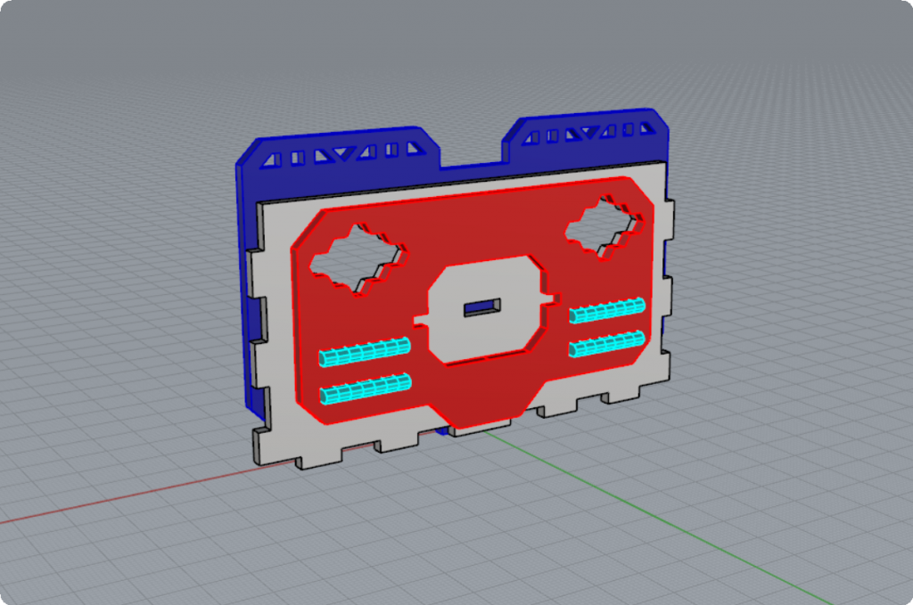
Once both the left and right units are inserted into the slots of the inner wall (grey above), we will now add the inside wall (red) as shown below:
Notice that the inside wall (shown in red above) also has two rectangular slots on each side which the “Power Generator” unit ribs fit into. This allows all three of the walls layers (blue, grey and red) to be easily aligned perfectly when you finally go to glue the pieces together.
Your kit will also come with two side windows which come in two variations. One variation is made from MDF wood which you can paint any color you like. The other variation is made from acrylic. It’s up to you which of the two options you choose for your side windows.
These side windows are meant to be glued into place.
You’ll notice that these side windows fit into place from the outer wall in and rest up against the inner wall (red above) hole. The inner wall hole for these windows was designed to be slightly smaller so that it’s easier for the windows to be glued into place without them falling through the hole.
Once fully assembled the side walls should look like this:
Repeat this process for the other side wall.
Assembling the Holo-Displays
Step 1 – Holo Display – Main Center Screen
The Holo Display is made up of three acrylic “Holo Screens” and the supporting mount and frames made out of MDF.
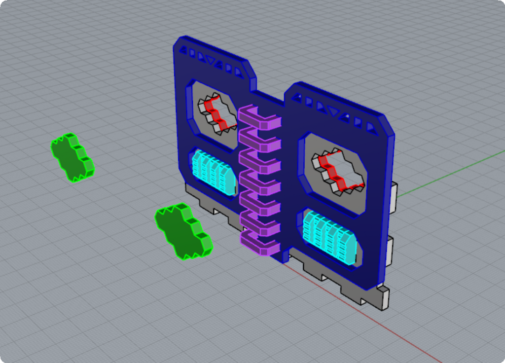
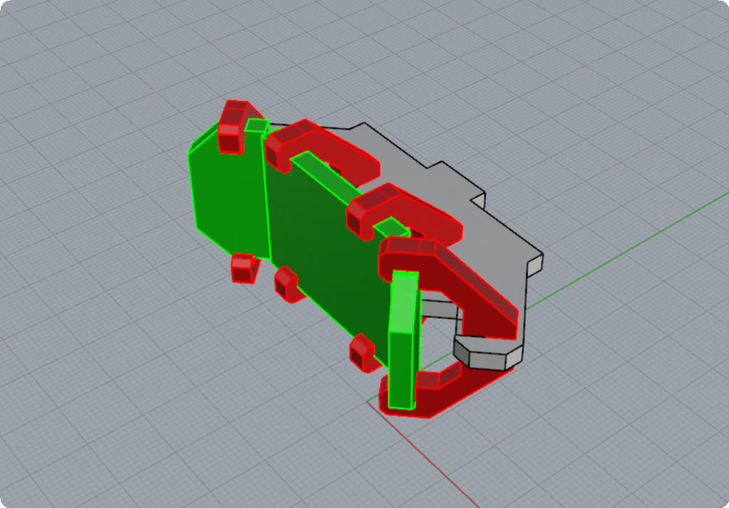
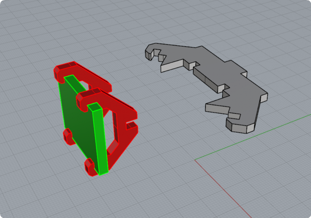
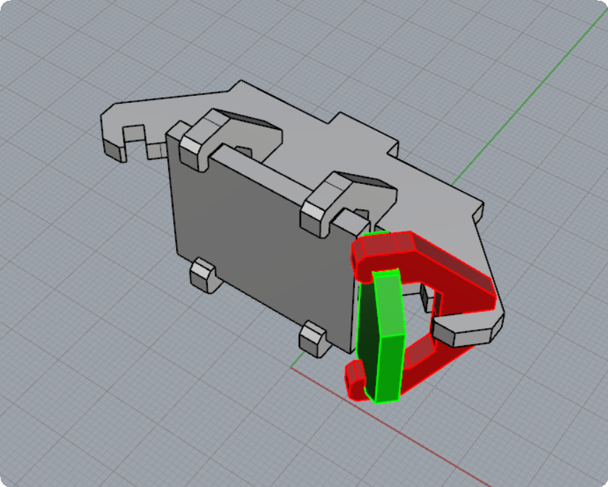
Locate the main center screen (shown in green above) for the Holo Display and two frame pieces (shown in red above).
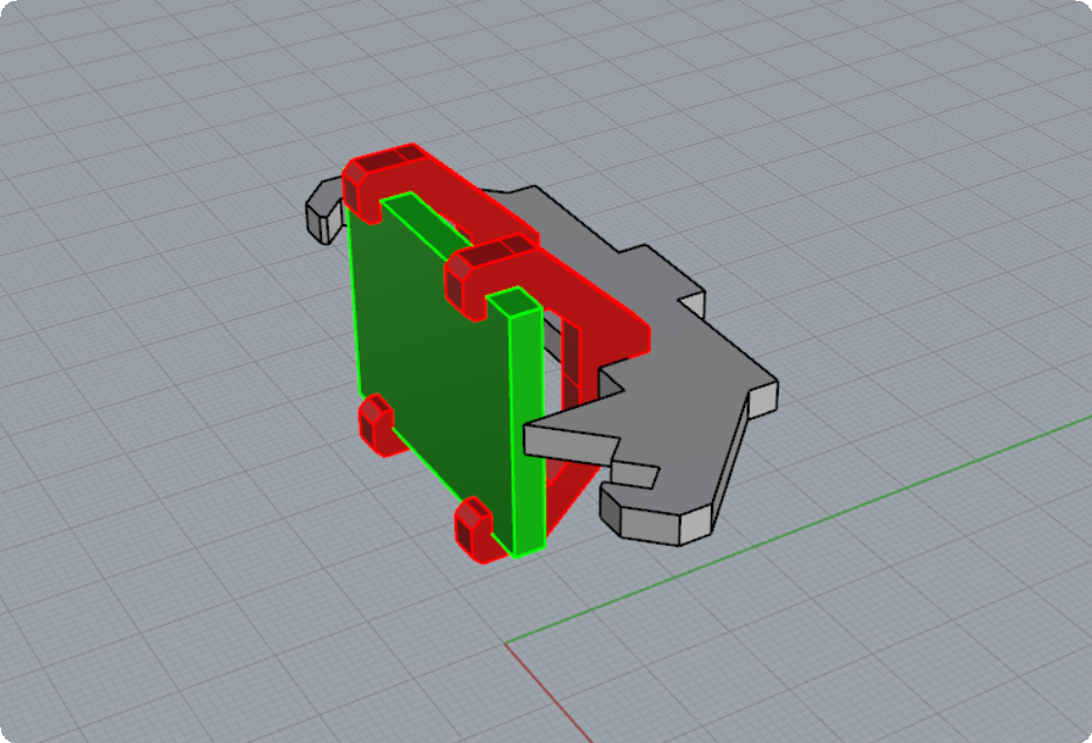
Slide the two frame pieces (shown in red above) onto the main center screen, and then carefully slide the three pieces into the main Holo Display mount (shown in grey above).
Once mounted, the Holo Display should look like this:
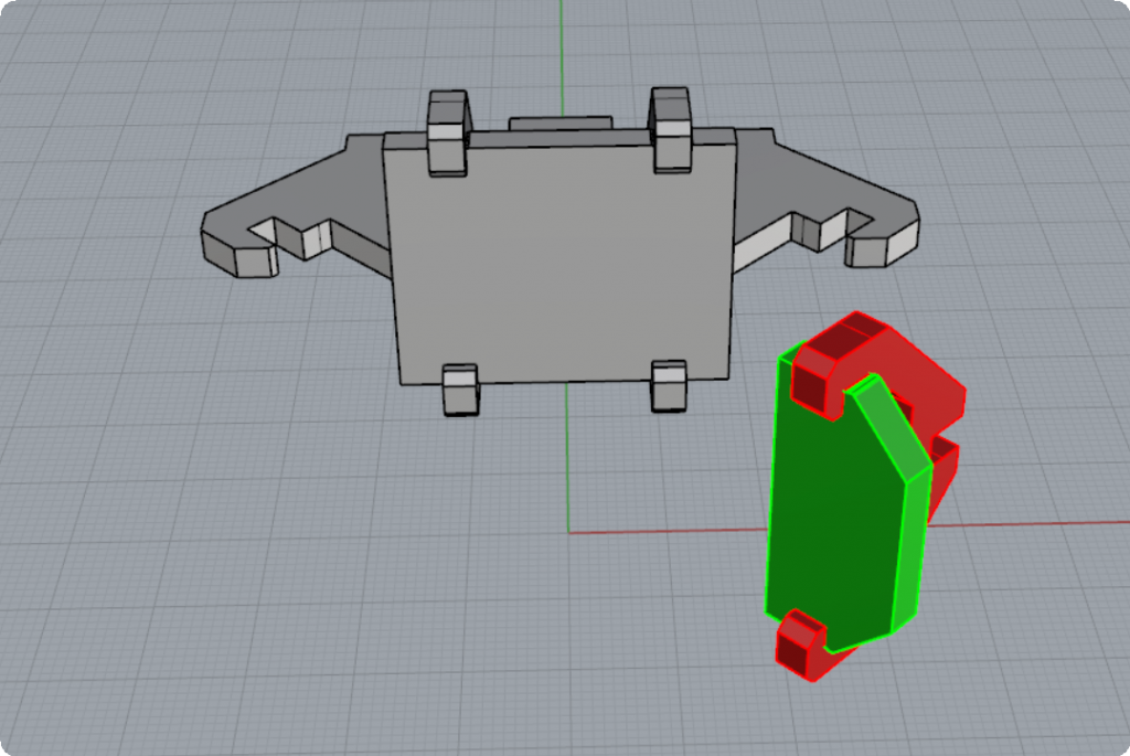
Next locate one side screen (shown green below) and another frame (shown in red below).
Place the side screen and frame into the Holo Display mount as shown below:
Repeat the process for the other side of the Holo Display to complete the build process.
Next, insert the entire Holo Display unit into the center slot of the side wall you assembled previously. Once assembled the side wall with the Holo Display should look like this:
Repeat the process for the second Holo Display for the second side wall.
Final Assembly of Hab Unit A
Once you have “dry” assembled each of the two front/back walls and the two side walls, you can now go back and glue all the pieces that require glue.
Remember that the windows and doors on the front/back walls are designed to slide out so they do not need to be glued (unless you want to permanently affix them).
Once you’ve glued all the individual pieces for all of the walls, you can now move onto assembling the building.
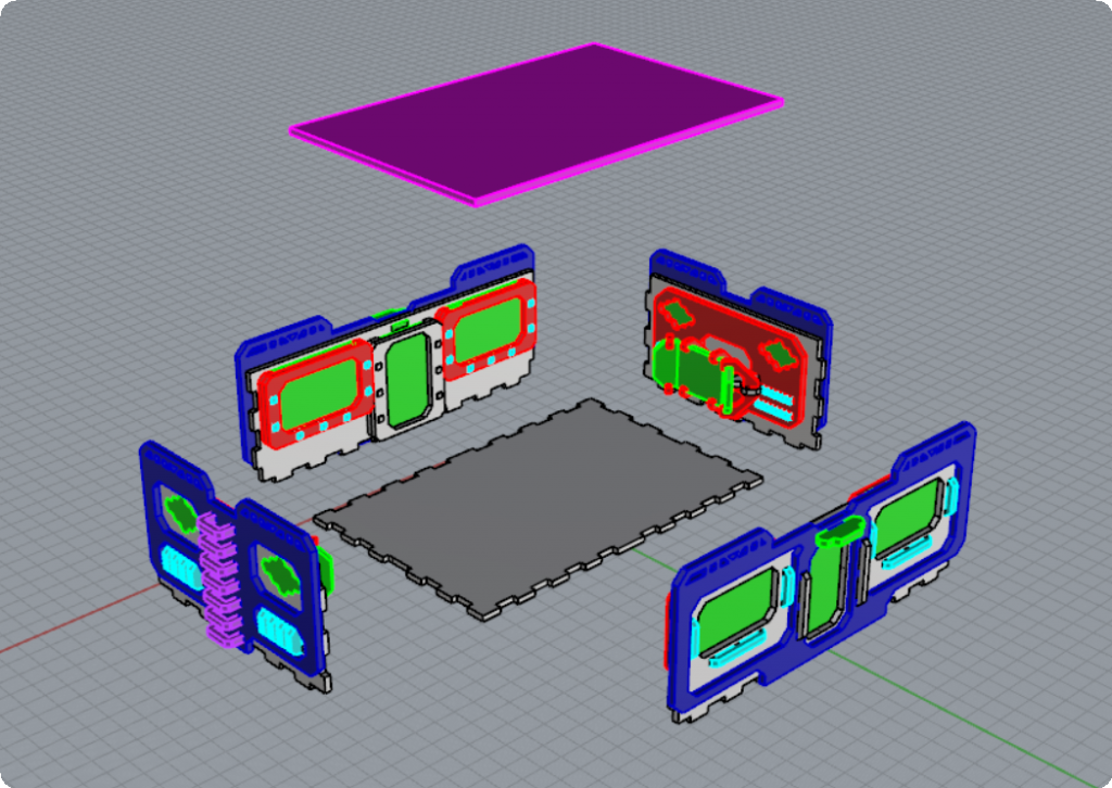
Place the floor piece on a flat surface. The floor piece is the large rectangular piece with the tabs on all sides as shown above in dark grey.
Do a dry test (without glue) putting all four walls together to get a feel for how all the walls fit together before gluing.
To glue the walls, use a wood glue putting a small dab of glue on each of the tabs on the floor piece as well as the tabs on the sides of the walls.
Ensure that all the wall pieces fit together to form a square edge on all sides without any gaps.
DO NOT glue the roof piece to the top. The roof piece simply sits on top of the building as a lid, and can be easily lifted by it’s sides in the middle just above the front/back door lights. You can lift the roof off to access the inside of the building and also to swap out the window/door pieces.
The completed building should look like this:
