Welcome Kickstarter Backers!
Below you will find some of the assembly instructions for your Victorian Steampunk Modular Terrain.
I’m still working on completing the instructions for all the modules and accessories and this page will be updated with new instructions as soon as they are available.
Until all the instructions are completed, feel free to contact me if you have any questions.
I have also setup a channel for Kickstarter Backers on Discord, which is a text chat application you can get setup with by clicking here -> https://discord.gg/VNXH2WM
Module Corner Clips
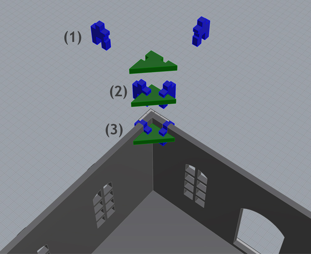
Your module will arrive with a set of clips which you will need to glue together and use to hold the corners of the modules together.
Each corner clip is assembled from three pieces you’ll find on your corner clips sprue, showed in the diagram above color coded in green and blue.
Step 1 – Punch out two of the clip pieces show above in blue, and one of the clip corners shown above in green. Please note that your clips sprue comes with two different kinds of corner pieces. Half of the ones you have on your sprue are LEFT handed, and the other half are RIGHT handed. You’ll need to assemble half of the clips LEFT handed, which fit into the left hand side of your modules, and the other half you’ll have to assemble RIGHT handed which fit on the right side of your modules. (See diagram below for examples of LEFT and RIGHT handed corner clips shown).
Prior to gluing your clips together, ensure you understand how they fit into the modules and what is meant by LEFT and RIGHT handed clips. If you try to take a LEFT handed clip and try to fit it on the right side of the module, you’ll see that it doesn’t fit and vice versa.
Step 2 – Glue the two clip pieces (shown in blue above) with the clip corner piece (shown in green above) with a small amount of glue and let the clip dry.
Step 3 – Insert the clip into the corner of the module, as shown above. Please note that if the clip doesn’t fit, you may be using a LEFT handed clip on the RIGHT side of a module or vice versa.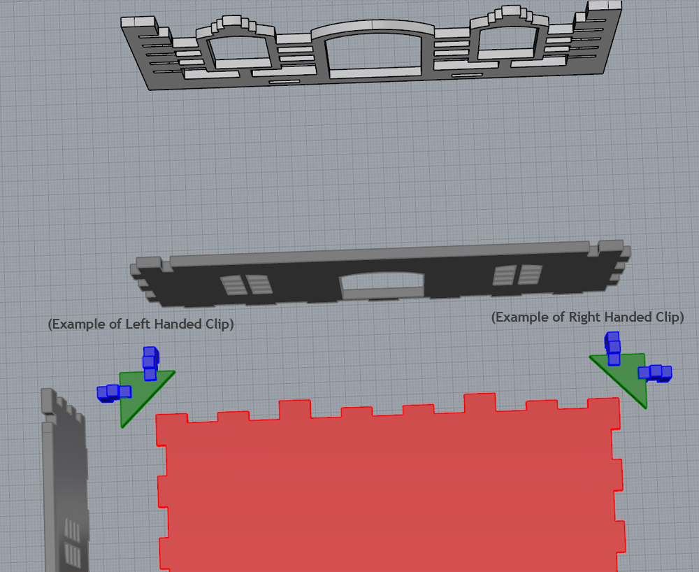
Module Assembly
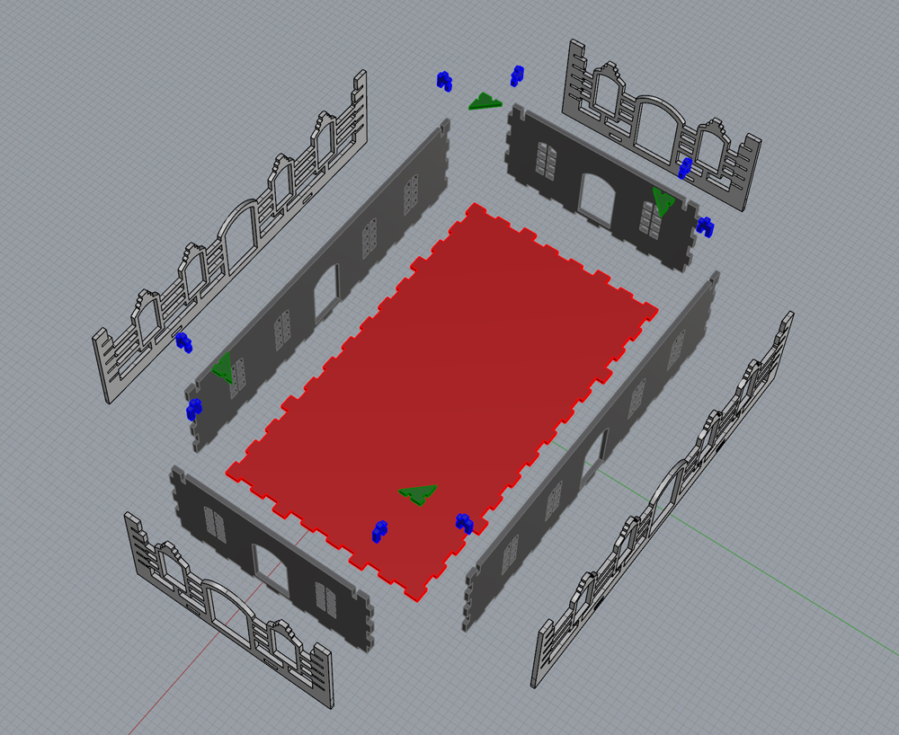
Each basic module is assembled starting with the floor (shown in red above), and then by adding the inner wall pieces (shown in dark grey above) to form a basic box shape.
Next, the outer wall pieces are added on (shown in light grey above).
Finally, the corner clips are slotted in on each of the four corners (shown in blue & green above).
Please note that by using the clips, the modules are able to stay together quite snugly without glue so gluing them together is optional at first.
This way if you want to be able to take the walls apart, switch out walls or take the pieces apart for painting you can do so before finally gluing the pieces together permanently.
Flat Roof
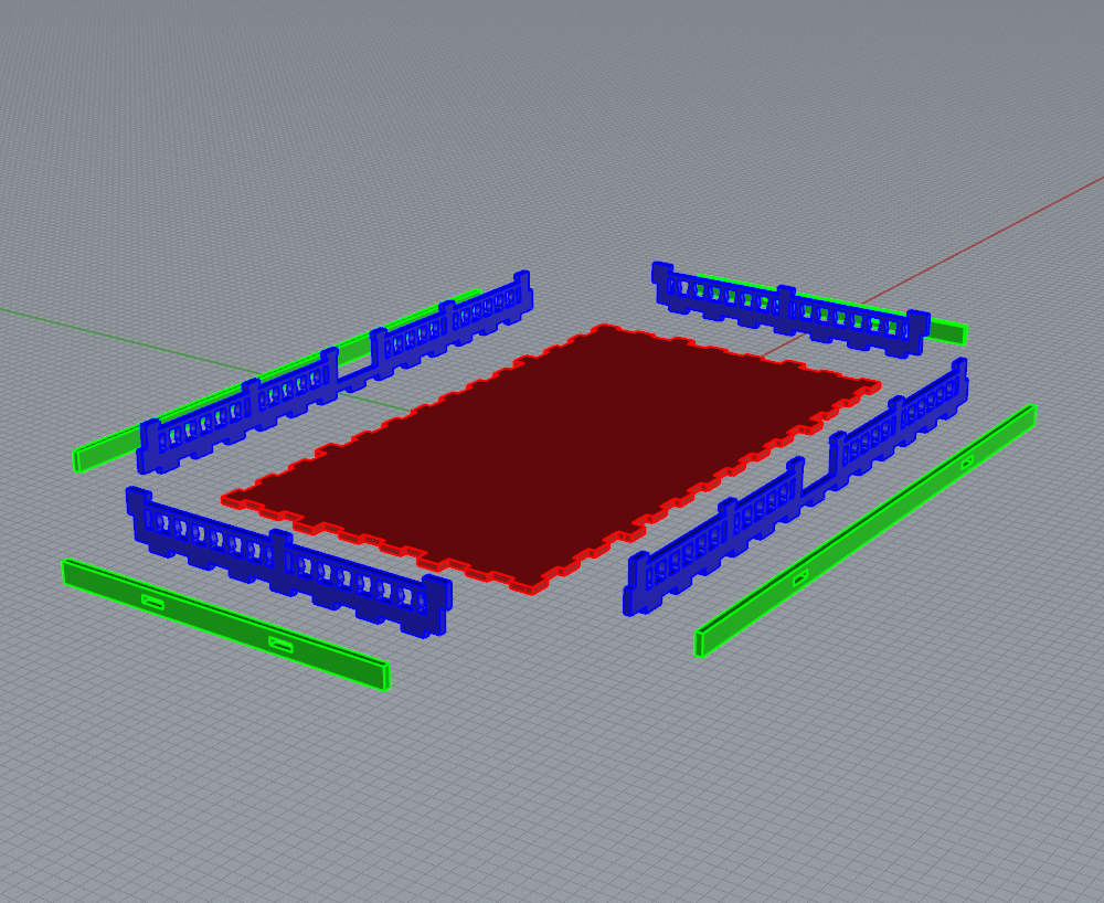
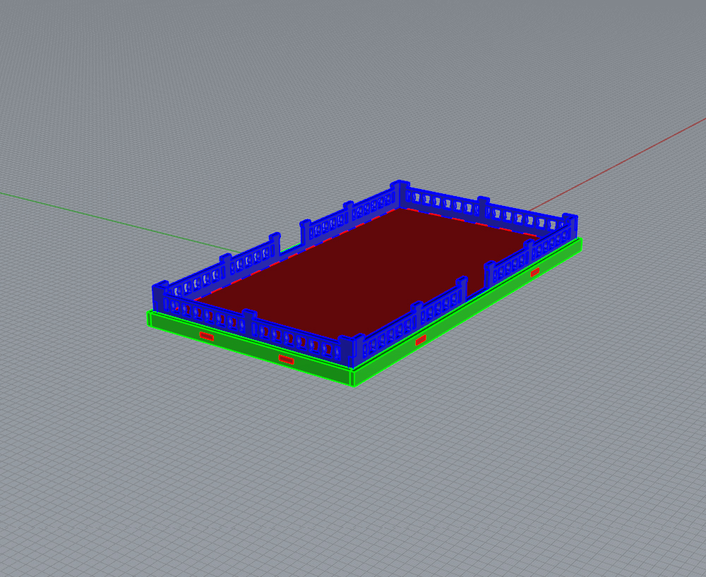
Each flat roof module is built from one floor piece (shown in red above), and eight decorative railing pieces (shown in blue and green above).
The assembly of the flat roof kits is pretty straight forward. The inner decorative railings (blue above) are attached to the roof floor first, followed by the outer pieces (green above).
The grid pattern on the roof floors can be assembled face up showing the grid or face down, hiding the grid.
Angled Roof
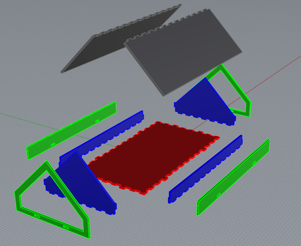
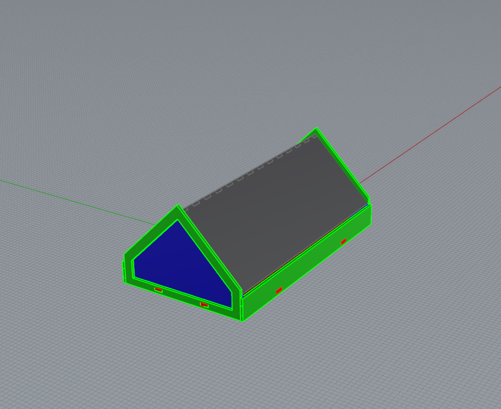
There are a number of different varieties of angled roofs available but they all assemble essentially the same way.
Each angled roof kit starts with a floor piece (shown red above), to which you attach two angled roof faces in the front and back (shown blue above) as well as two side pieces (also shown in blue above).
Next you attach the outer face of the roof (shown green) as well as the outer side pieces (also shown in green).
Finally, you attached the two roof tops (shown in dark grey above).
Please note that the various different angled roof tops will have different looking roof faces, but they all assemble the same way as shown above.
Skylight
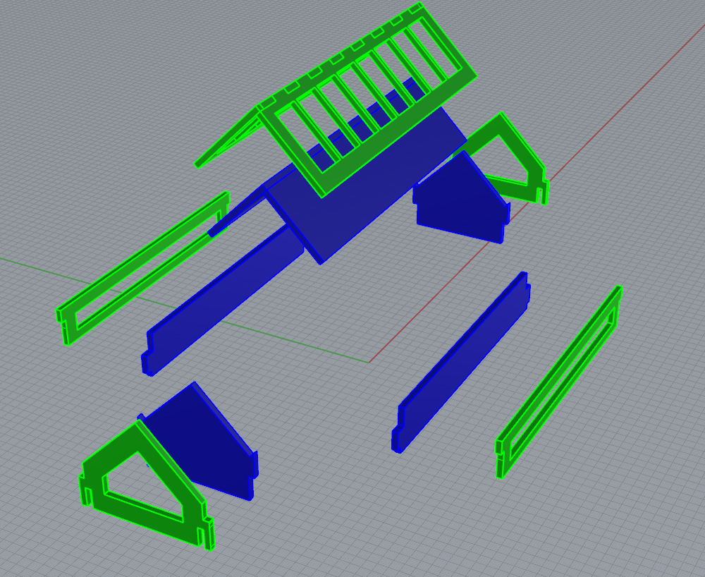
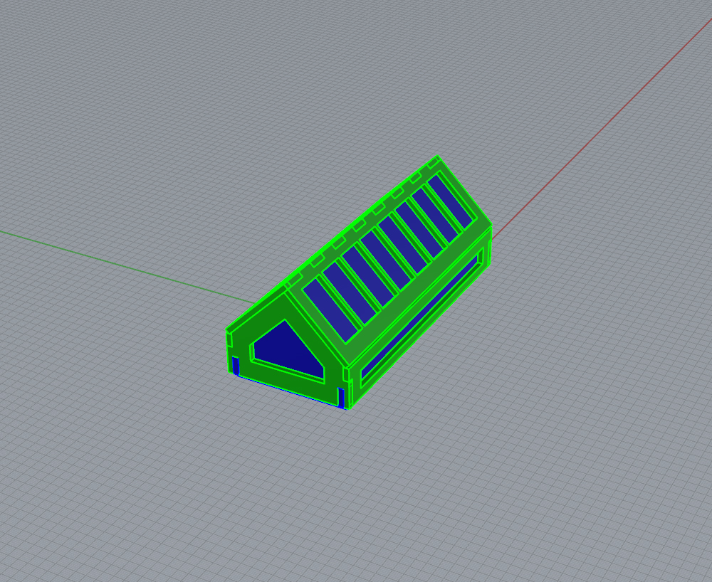
The skylight roof kit is built out of two main parts.
The first part is a basic flat roof kit with a large rectangular hole cut out of the roof floor. Please refer to the flat roof assembly diagrams on this page for assembly instructions of the flat roof.
The second part is the actual skylight itself which is made up of six acrylic pieces (shown blue above) and six MDF wood pieces (shown green above).
To start, assemble the front and sides of the acrylic pieces as shown above.
You can “dry fit” the pieces together without gluing at first by sliding on the front and back wooden face (green above). It should slide onto the acrylic pretty snugly and hold the pieces together.
You can then “dry fit” the wooden side pieces and finally the acrylic roof top and MDF wood window covers.
Once you see how the whole skylight goes together you should be able to slide it into the hole of the flat roof. It will fit in there pretty snugly.
Once you’ve “dry fitted” everything and know how it goes together you can go back and now glue the pieces together, starting with the four acrylic pieces first (front, back, sides) and then gluing the wooden front/back and sides and then finally the roof of the skylight.
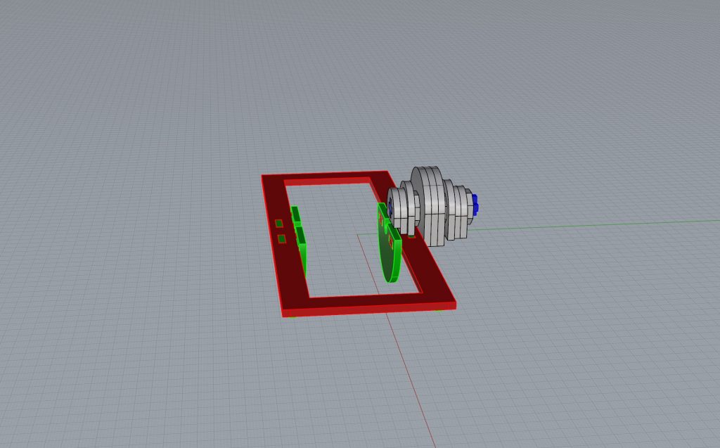
Power Station Water Wheel
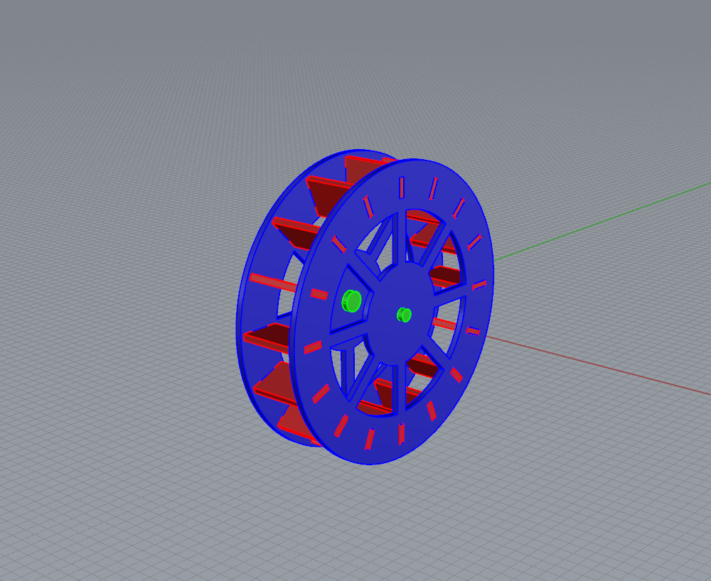
Power Station Towers
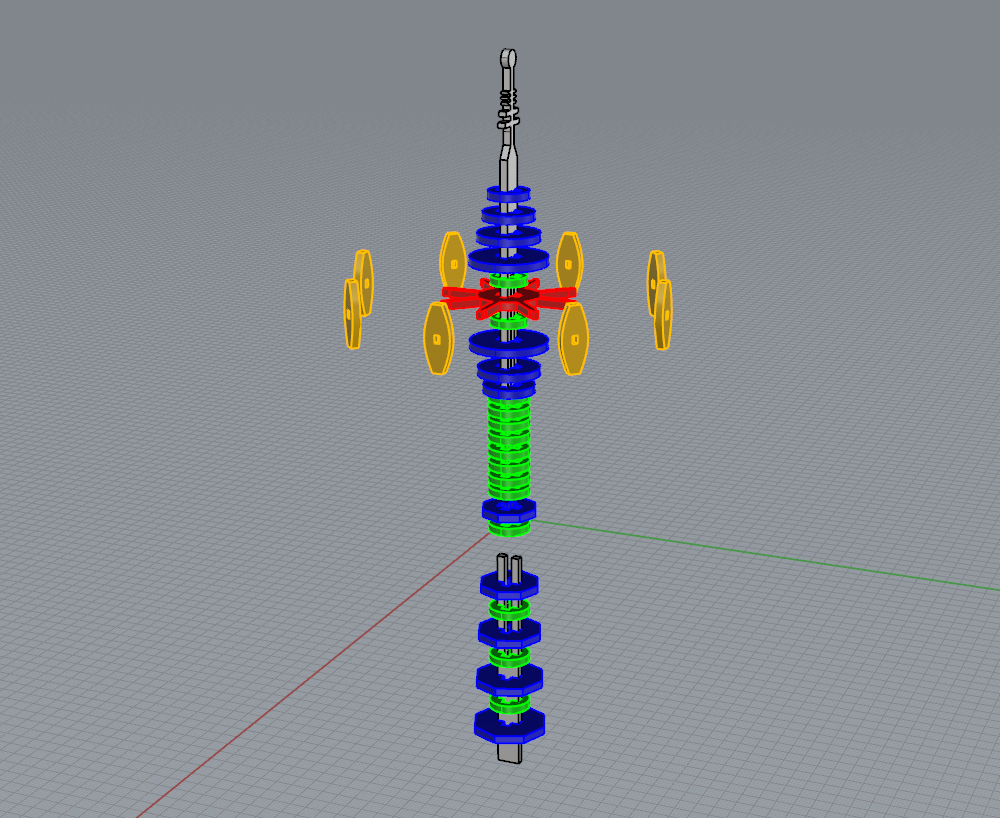
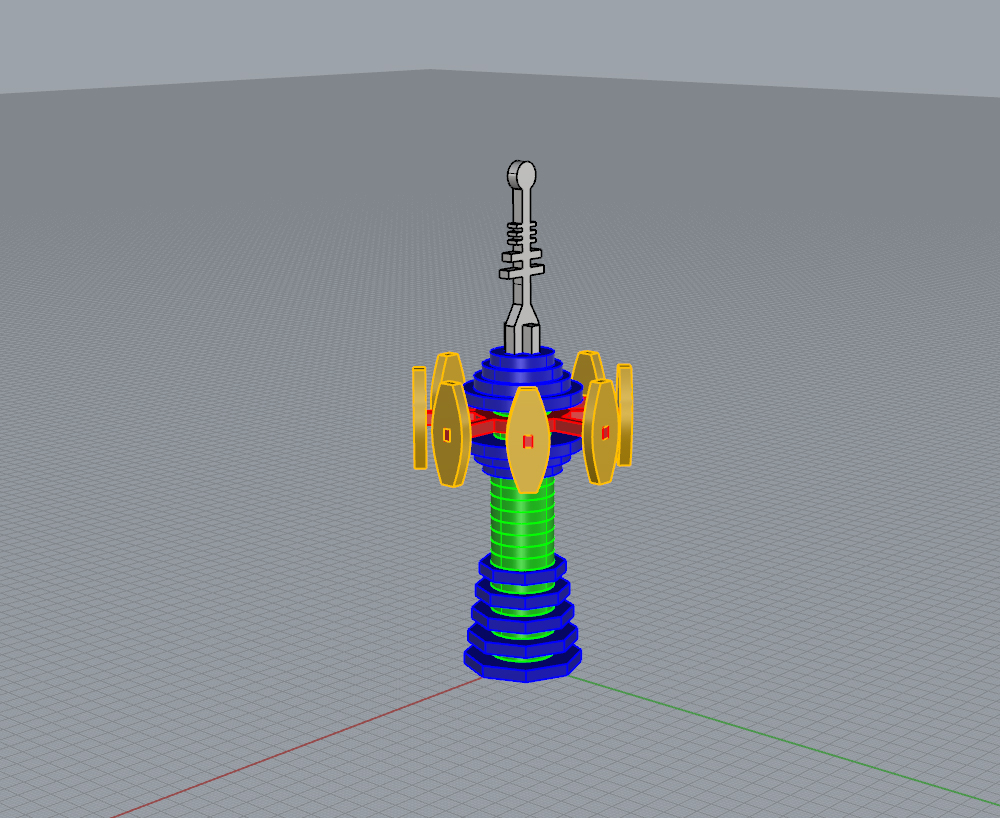
Power Station Generator
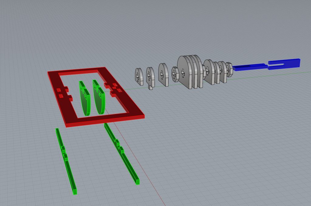
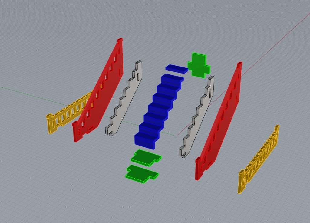
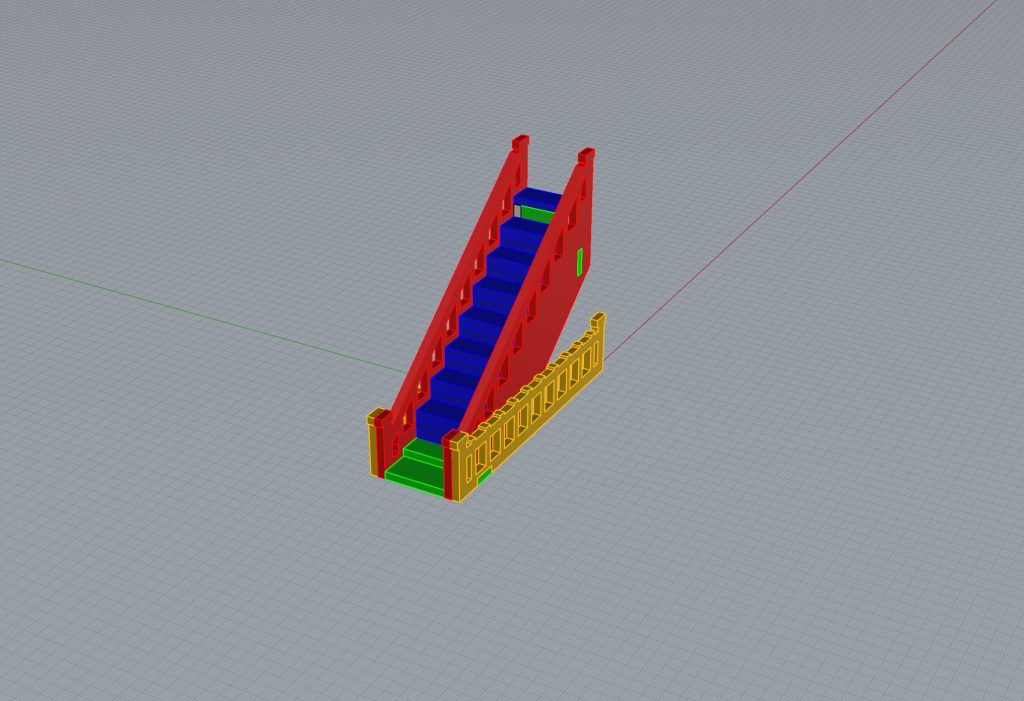
Staircases
